You are not required by the Standards of Practice to open service panels!
- Service Panel Inspection Checklist
- Federal Pacific Stab-Lok Hazards
- Square D QO model RECALL (Plant 15 panels only)
- QO models can be recognized by the tripped indicator. Square D Home line models do not have this indicator.
- Zinsco Panel Hazards
- Backfed Breakers
- Neutral Conductor Concerns
- Types of Panelboards
Photograph it, especially grounding and bonding components, labels (including SE/feeder conductor markings), and defects.
Safety
- Wear personal protective equipment (PPE), including glasses and gloves. Avoid synthetic clothing.
- Use proper inspection tools, including voltage detector, insulated handle screwdriver, and flashlight.
INSPECTING LOAD CENTERS
Panel location
- Identify panel location:
- Readily accessible and protected from physical damage
- Damp/wet locations: electrical cabinet must be shielded from- or approved for- wet locations. Cabinets installed in damp locations should have a ¼" (5mm) minimum air space between the cabinet and the wall.
Compliance with minimum clearances
-
- The working space in front of the cabinet should be a minimum width of 30" (76cm). 2017 NEC 110.26 Spaces About Electrical Equipment
- A minimum space of 3’ (1m) from a non-fireproof ceiling;
- The working space in which the cabinet is located should have a minimum headroom of 6’-6" (2m)
- Maximum height 6’-7" (2m) to center of breaker switch in on position.
Adequate illumination at interior-mounted panels
Adequate mounting
-
- Proper anchors into masonry, concrete, plaster, etc. 2017 NEC 110.13 Mounting and Cooling of Equipment
- Flush mounting: when cabinets are mounted in cavities in non-combustible materials, the front edge of the cabinet should be recessed no more than ¼" (5mm) back from the face of the finished wall surface. 2017 NEC 312.3 Position in Wall
The panel should not be exposed to potentially damaging conditions
-
- Temperatures above 104°F (40°C);
- Corrosive or explosive fumes, dust, or vapors;
- Abnormal vibration, or mechanical shock/impact;
- Tilting or unusual operating conditions;
Exception: if the panel has been designed to accommodate a particular condition and is identified as such by the manufacturer.
Unused openings should be filled with a component designed for the purpose.
Main Disconnect
Disconnect Safety
- Never operate a disconnect when the cover is open. Modern disconnects have door interlocks that prevent the handle from being turned on when the door is open, but they can fail, or they can be defeated.
- Always wear gloves and safety glasses around electrical equipment;
- Turn your face and body away from the disconnect before operating the handle.
- Never turn a disconnect off while the equipment it feeds is running, unless it is an emergency.
Inspecting the Disconnect
- Identify Amperage;
- Evaluate condition;
- Confirm marked as main disconnect;
- Identify lack of a single disconnect;
- Identify as defective if more than 6 switches must be operated to shut off all circuits.
Fused Disconnect with a Load Center
A fused disconnect is a disconnect that relies on a fuse instead of a breaker to shut down power to a circuit in response to a ground fault or short circuit.
When a fused disconnect is installed upstream of a load center (making it the "first point of disconnect") the fused disconnect is the service panel and must have its own grounding electrode conductor (GEC) connected to a grounding electrode. It's in this cabinet that the neutral bus bar will be connected to the grounding bus bar, to the panel, and to the GEC. In other words, this is where the main bonding jumper will be located.
In this configuration, the load center, even if it has a main disconnect, is just a sub-panel, and the neutral bus bar should float (be electrically isolated from the metal cabinet and from the grounding bus bar). A single neutral conductor should connect the (floating) neutral bus bar in the load center to the fused disconnect.
- If the fused disconnect and the load center are remote from each other (in separate buildings, no min. distance given), the load center should have its own GEC and grounding electrode.
- If the fused disconnect and the load center are installed at the same building, only the service panel (fused disconnect) would be connected to a grounding electrode.
- If for some reason the fused disconnect service and the load center are installed at the same building and each has a grounding electrode installed, the electrodes would need to be directly connected by a conductor of adequate size to avoid creation of stray electrical current traveling through soil between grounding electrodes at different electrical potential.
Inspection of Fusible Disconnects
If a fusible disconnect is located upstream of a load center at the home, the fusible disconnect is the service where neutral/ground bonding takes place. It should have a GEC and grounding electrode.
If the fusible disconnect location is remote from the home, the load center should have its own GEC and grounding electrode, but the neutral bus bar should float. Under these circumstances, the load center is just a sub-panel.
Dead Front Cover
- Test for current present on the dead front cover;
- Confirm correct screw types used. If incorrect, don’t open and disclaim, recommend correction;
- Check for missing filler plates;
- Comment on any breakers in the "Off" position;
- Examine and photograph labels and other written information;
- Manufacturer’s label
- ID manufacturer
- Zinsco, Stab-lok, Sylvania, Westinghouse panels may be problems
- Listed amperage rating
- Identify amperage rating defects related to panel. disconnect and service entrance conductors.
- Circuit Directory
- Presence and legibility
- Apparent integrity (comment if altered, or appears out of date)
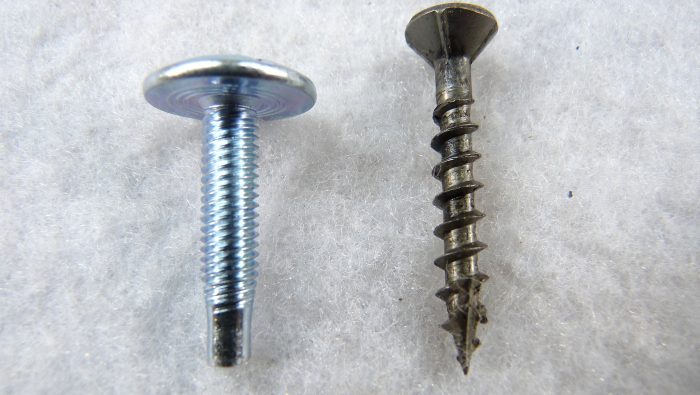
Left: proper cover screw Right: Pointed, course thread screws may cut conductor insulation, energizing the panel or causing a dangerous arc flash.
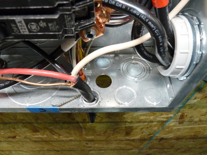
Panel Cabinet
- Free of debris, paint/drywall overspray, etc.;
- No open knockouts
Service Entrance Conductor Connections
- Identify proper service entrance conductor connections to panelboard;
- Identify back feed conditions;
- Confirm back feed breakers are held in place by a clip.
PANELBOARD GROUNDING AND BONDING
GROUNDING
SERVICE GROUNDING
- The electrical system should be connected by a grounding electrode conductor (GEC)—using a clamp listed for that purpose—to a grounding electrode installed in the soil near the service panel.
Grounding Electrode Conductor Minimum Sizes
- 6AWG copper or 4AWG aluminum or larger if the only electrode is a single driven metal rod/buried pipe
- 4AWG or larger if the only grounding electrode is rebar in the footing.
- The grounding electrode conductor (GEC) should be connected to the grounded (neutral) service conductor at an accessible point between the service point (splice at drip loop) and the neutral bus bar in the service panel. The neutral bus bar is the most common point of connection.
- The electrical system should be connected to a grounding electrode or electrode system. Only three types will be visible:
Visible Grounding Electrodes:
- Metal underground water pipes may serve as grounding electrodes in some jurisdictions. This was common in the past . The GEC should be connected to the pipe within 5’ of the point at which it enters the ground. If an inline water meter is installed between the grounding clamp and soil, a jumper should be installed to electrically connect the pipe on each side of the meter. Do not mistake a bonding clamp and conductor for a grounding clamp and conductor. A bonding conductor will probably connect to a hot water supply pipe or a junction box.
- Ufer grounds are acceptable as service grounding. A Ufer ground is steel rebar encased in a concrete footing. The rebar is bent to protrude from the footing, providing access for clamping the GEC. Access is often in the garage, typically behind an access cover a couple of feet above the floor.
Grounding Electrodes that are not visible:
The following types of grounding electrodes are acceptable, but not visible. Ask for documentation:
- Driven rods are the most common. They are required to be driven to their full 8’ length, but you will not be able to confirm length visually, so you should disclaim it’s proper installation and performance. Rods may be driven at an angle not to exceed 45°.When two 6’ rods are used they should be placed no closer together than 6’. Sometimes you can see the top of the rod, sometimes not. The GEC should be connected with a listed (proper) clamp.
- ground ring: a ground ring is a buried bare copper conductor that encircles the structure that it protects.
- plate electrode
NOTE: In most jurisdictions, gas pipes should NOT be used as grounding electrodes (although they should be bonded. Again, don’t mistake bonding components for grounding components).
EQUIPMENT GROUNDING
- Grounding and grounded (neutral) conductors must terminate on separate bus bars in sub-panels but may terminate on the same bus bar in the service panel.
- Each grounding and grounded (neutral) conductor should terminate on an individual bus bar terminal that is not also used for another conductor. In other words, only one conductor per hole. However, instructions on the label may permit more than one grounding (EGC) conductor of the same size per terminal. Neutrals must always terminate separately.
BONDING
Definition:
Bonding is the use of conductors, straps, screws, and other types of electrical components to establish electrical continuity between various metal components that enclose electrical conductors or equipment; between all metal components that might accidentally become energized.
Components that are commonly bonded are:
- Electrical service masts;
- Electric meter housings;
- Load center cabinets;
- Metal conduit;
- Water supply pipes; and
- Usually gas pipes(varies by jurisdiction)
Bonding INSIDE the service panel
- Main bonding jumper. Grounding and neutral bus bars should be bonded together (only service panels, not in sub-panels);
Common methods that directly tie the bus bars are:
- Tie bar;
- Bonding jumper (if conductor, no smaller than GEC)
Common methods that bond the bus bars by connecting them to the back wall of the cabinet are
- Bonding straps;
- Bonding screws (green);
- Mounting bus bars directly to the back wall of the cabinet.
Acceptable Bonding Connectors
OK:
- Conductors (adequate size);
- Threaded couplings and hubs;
- Threadless (compression) connectors;
- Bonding locknuts, bushings and wedges. (will have screw);
Not OK
- Standard locknuts
Bonding OUTSIDE the service panel.
Any metal components that contain current-carrying conductors should be bonded both to each other, and to the grounded (neutral) service conductor. Some jurisdictions may not allow bonding of gas pipes.
Components commonly bonded are:
- electrical mast;
- meter housing;
- metal conduit; and
- any metal raceways.
Components that may accidentally become energized should be bonded to the rest of the electrical system:
- metal water and gas pipes. Look for bonding clamps near water heaters, and for bonding conductors at points where pipes pass near a junction box, the service panel or a sub-panel.
NOTE: In sub-panels, neutral bus bars must float, i.e., must be electrically isolated from the grounding system. Check to see that green-colored bonding screws have been removed, that the neutral bus bar is attached to the cabinet by an insulating material, or that other methods have been used to ensure electrical isolation of the neutral conductor.
Bonding in Sub-panels
- floating neutral bus bar. Neutral bus bar must not be bonded to the cabinet or grounding bus bar.
- No fused neutrals.
PANEL WIRING
- Identify wiring type;
- Look for damage (nicks) to bare conductors where insulation was stripped for attachment to breakers and bus bars;
- If conductors are bent to 90° angles, look for broken insulation at the outsides of bends;
- Comment on loose or disconnected wires;
- Aluminum conductors should have anti-oxidant applied at connections and in older homes connections should be tightened periodically;
- Discoloration or flaking of insulation indicates overheating;
- Pitting at connections indicates arcing.
- Comment on any backup generator wiring
BREAKERS
- Signs of overheating;
- Multiple conductors at connections made for one conductor;
- Loose or damaged breakers
- Improper brands/types;
- Note presence of GFCI/AFCI
Testing GFCI Outlets
When testing for GFCI protection of electrical circuits by activating the trip button on a 3-light testing device, the inspector may then be unable to locate the GFCI outlet controlling the circuit to which he has shut off power. Affected outlets are sometimes in another part of the home or hidden behind the occupant’s belongings. Using the test button built into GFCI outlets will prevent this problem.
LABELS
Manufacturer’s Label
Depending on the age and manufacturer, you may see different information on the label. Photograph the label, especially the parts with amperage rating and bonding diagrams. Here is the information you will look for:
- The amperage rating of the panel. This rating must not be less than that of the main disconnect. This is the most important information on any label.
- The exposure rating of the panel. This is a number code that corresponds to the locations in which the panel is designed to be installed (interior, exterior, raintight, rain resistant, rain protected, etc.)
-
- Type 1, rated for indoor use primarily to provide a degree of protection against limited amounts of falling dirt.
- Type 3R, rated for outdoor use primarily to provide a degree of protection against rain, sleet and damage from external ice formation.
- Type 3S, rated for outdoor use primarily to provide a degree of protection against windblown dust, rain and sleet; external mechanisms remain operable while ice-laden.
- Type 4, rated for indoor or outdoor use primarily to provide a degree of protection against splashing water, windblown dust and rain, hose-directed water, and damage from external ice formation.
- Type 4X, rated for indoor or outdoor use primarily to provide a degree of protection against splashing water, corrosion, windblown dust and rain, hose-directed water, and damage from external ice formation.
- Type 6, rated for indoor or outdoor use primarily to provide a degree of protection against hose-directed water, the entry of water during occasional temporary submersion at a limited depth, and damage from external ice formation.
- Type 12, rated for indoor use primarily to provide a degree of protection against circulating dust and falling dirt.
- Type 12K, rated for indoor use primarily to provide a degree of protection against circulating dust, falling dirt and dripping non-corrosive liquids.
- Type 13, rated for indoor use primarily to provide a degree of protection against dust and spraying of water, oil and non-corrosive coolants.
- Grounding and bonding diagram- important in identifying the bonding screw.
- The listing agency certifying that the equipment complies with manufacturing standards, typically ANCE, UL, or may be both.
- Whether it is designed as service equipment or a distribution panel .
- The number of phases and voltage for which it as designed- typically single phase 120/240 .
- The number of circuits it is designed to contain. This means full size circuit breakers. This number may be improperly exceeded if duplex, triplex or quadplex breakers are used. Lighting and appliance branch- circuit panelboards are allowed a maximum of 42 poles. That’s 42 switch handles.
- The maximum overcurrent device short circuit voltage- typically 10,000v.
Check for:
- Amperage rating defects:
- Main disconnect must be rated greater than the:
- Service entrance conductors
- Cabinet;
- Non-compliance with listed information.
Circuit Directory
The Circuit Directory should be in place, legible, and accurate. If it looks older than the electrical work you see, recommend confirmation by a qualified electrical contractor.